How to erect cfbc boiler
- 1. STANDARD ERECTION MANUAL (Pressure Parts) Prepared by Power Sector – Technical Services (HQ)pune Corporate Quality Assurance Bharat Heavy Electricals Limited, New Delhi 1
- 2. 2
- 3. INDEXSL. No. TOPIC Instruction No.1.1 Introduction I - 01 - 0201G1.2 Pressure Parts Erection Sequence1.3 Pressure Parts Components2 Boiler Drum B1 - 0I - 0202T3 Erection of Headers B1 - 01 - 0203T4 Erection of water walls, headers B1 - 01 - 0205T6 Down comer erection B1 - 01 - 0206T7 Erection of steam cooled walls B1 - 01 - 0207T and SH / RH/ EVAP. / ECO. COILS FBHE Header and Coil Erection8 Buckstay erection B1 – 01 - 0208T9 Air And Gas Tightness Test (Boiler) B1 - 01 – 0212T10 Annexures10.1 Manpower, Requirement. B1 – 01 - 0213T10.2 Bar Chart B1 – 01 - 0213L10.3 Erection Record of Formats B1 – 01 - 213 G10.4 Reference Documents B1 – 01 - 214G 3
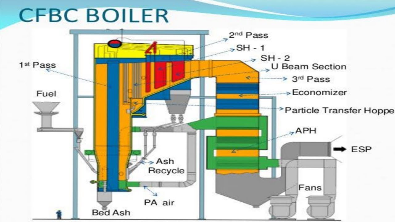
- 4. BOILER PRESSURE PARTSIntroductionThe general arrangement of pressure parts of a conventionaldesign boiler of 250 MW unit is shown in Fig.1: combustorarea and Fig. 2 (back – Pass. The locations of Pressure partcomponents and assembled are also indicated in the figures.At job site, the main function of erection group is to receivethe components, store them, protect them from damage,preserve them during storage to sustain the originalcondition and assemble them which the permissiblelimit/tolerance specified in the Pub 2022 to achieve pre-determined performance during operation.Around 5600 MT of pressure parts components per unit aredispatched loose to the job site by road and rail. Hence, itbecomes all the more important for the job site erectiongroup to take utmost care right from the receipt stage tocompletion of erection, so that commissioning activities canproceed without any difficulties.The major components in pressure parts to be erected areboiler drum, headers, water – walls and stream cooled walls,super – heater and reheater coils, buck – stays.Recommended hydraulic test procedure, welding & NDEalso covered in this section. 4
- 5. 3…… Pressure Parts Erection Sequence3.1 Boiler Drum Erection: Before starting Pressure erection study FQP on pressure part carefully and understand acceptance criteria. FQP on pressure parts is hyper linked with text here. Minimum structure to be erected is referred in FQP on structure which is hyper linked. Approx. 3850 MT structural weight is to be erected before drum lifting as enclosed in table.3.1.1 Preparatory works: Like in conventional boilers, drum is dragged and placed at ground just below its permanent position in between combustor and back pass. Boiler Drum is inspected on ground prior to erection on receipt. It should be shifted under boiler structure carefully. Obtain statutory clearance as applicable. There is approximately 3850 MT to be erected prior to boiler drum erection. Following members should be erected and welding completed. These structure arrangements are identified as – First pass – accommodating furnace. Middle Walls FBHEs, air / flue ducts etc. Second pass- accommodating boiler drum, steam cooled SH, SH III, SH IB, RH II. Economizer etc. Third pass- accommodating FBHE Air pre-heater (tubular type) and quad sector regenerative air pre- heater with inter connecting duct – work. Total number of column 38 nos. Height of the column maximum 63.750M Number of column tiers 05 nos. Bracings vertical and horizontal, trusses etc. 1.1.2 To carry out Dimension checks as per FQP. To be recorded 1.1.3 Final dimensions of combustor and second passes 5
- 6. 1.1.4 Final dimensions of third pass (APH) To be recorded Temporary Cat Head lifting structure is locally fabricated (after vetting of engineering for the design) and erected. If decided for Stand jack system, the lifting equipment is placed and approach plat form is made at ceiling girder level. Similar of conventional boilers, all arrangements for strand jack equipment emergency power, sheaving etc are carried out. Mark and punch position of washer plates over the drum suspension welded beam and cross check the same with respect to boiler and drum axis. Take the diagonal of washer plate center to center, if required adjust It. Mark and punch the center and angle over washer plate. Assemble rocker over washer plate wrt O Movement as given in the drawing. Erect all washer plate along with rocker over welded beam where drum is to be suspended. Check axis measurement once again and fill up long sheet. The axis mark on suspension rod with drum should be ensured. Mark and punch.3.1.2 Strand jack method is used for drum lifting. Wire rope of 20 meter length for lashing multi sheave pulley block at cat head and 40 meter rope for lashing multi sheave pulley clock with drum is used. o The co-ordinates of drum lifting structure is checked from boiler axis. LPI/ DPT checks are carried out for welding of structure. The main hoisting pulley blocks are attached to drum is safe manner with minimum 8 to 10 turns on each side. The axis of top and bottom pulley blocks should be in one line. The wire ropes clamps should be checked for correct size capacity, quantity, tightness and positioning. The anchor end of the wire ropes at pulley blocks at winch point and drum point should be checked for safety. Avoid over lapping of wire ropes.3.1.3 Total operation from start of lift to release of load of electrical winch usually takes 06 to 07 hours. 6
- 7. Crane or electrical winches can lift the drum. ESP – erection can be preceded as a parallel activity. Refer section 05 for details. Pressure parts erection is undertaken in following sequence. Similar to conventional boilers, furnace and second pass were erected from top to bottom.3.2 Furnace: Following sequence is followed. 3.2.1 Roof pre- assembled and lifted to position 3.2.2 Building up front, rear, right and left side water wall 3.2.3 Upper panels 3.2.4 Inter panels + upper panels buck – stay 3.2.5 Pent leg panels 3.2.6 Pent leg buck stays 3.2.7 Down comer, riser, inter connecting links / pipes etc as and when availability of fronts and materials.3.3 Second pass Following sequence is followed 3.3.1 Roof pre- assembled and lifted to position with hanger tubes 3.3.2 SCW SH upper panels 3.3.3 Final SH III 3.3.4 SCW SH lower panels 3.3.5 RH II coils 3.3.6 Evaporator 3.3.7 Economizer 3.3.8 Buck – stays / support matching to next stage of erection 7
- 8. 3.3.9 All inter connection links / pipe, headers + loose tubes failing outside the second pass panels, gas ducts as per available of materials. 3.3.10 Complete FBHE Casing 3.3.11 Then refractory work on FBHE Casing should be completed. Refractory Dry out can be done at latter stage. 3.3.12 Erect FBHEs coils3.4 All balance pressure parts are erected as parallel activity, comprising of the system from economizer inlet feed line isolation / NRV to main steam line isolation valve at boiler end consisting of all links, drains, vents, expanders, filling line, sampling line, chemical dozing lines, fine fittings etc, with all supports.3.5 Since combustion is pressurized, all attachments panel to panel are to be seal welded totally from outside and inside after back gouging. LPI test is done for ensuring quality seal welding. Approximate 12 kms of seal welded is done totally. Inside seal welding app 6 kms, which are not covered by refractory of combustor are flush ground to avoid erosion/ turbulence of hot flue gas / ash during operation. Second pass is having negative pressure, therefore it is seal welded typical to conventional boilers.4. Insulation: refer section 07 for details Mineral wool insulation pins outside the first / second pass walls, all refractory holding down / anchoring parts inside combustor. FBHEs. Seal pots and all attachments are fully welded. After a through inspection of all completion of work and protocols completed, total system is tested with compressed air and leaks noticed are attended.5. Erection Works completion for Hydraulic Test of Boiler Major pressure parts works for hydraulic tests are: Pressure parts 5600 MT* HP joints – physical 35000 Nos.* Refractory iron components 16 MT* Sea welding of furnace, FBHE and second pass 20 Kms* 8
- 9. Note: * indicative quantity for exact quantity refer drawings as applicable. Platforms Hydraulic test procedure is followed as enclosed in section 14. 9
- 10. PRESSURE PARTS COMPONENTS 10
- 11. 11
- 12. 12
- 13. PRESSURE PARTS 13
- 14. 14
- 15. 15
- 16. 16
- 17. I. Boiler Supporting Structure – Requirements 1. Boiler supporting required for drum lifting to be erected 1.n all respects including alignment and full welding and cleared for drum erection. Joint inspection protocol for completion for structure prior to drum erection are to be filled and cleared for drum erection. (Refer checklist BR(STR) – 200 /210 -92 & Log sheet No FQA – O1-35-00- L12. 2. Identify one main column (preferably S9 –or S10 – left or right) for all elevation measurement, to avoid column to column elevation marking variation. 3. Punch mark the elevation of drum (elevation shown in the Contract erection drawing) on the identified column for drum alignment.II. Calibration Requirements 1. All the measuring instruments are to be identified and registered as per FQA System F- 15 and guidelines for calibration F – 15 /GL – O1. 2. Calibration label (F -15 -02 are to be fixed on the instrument, with duly filled details like registration no, next calibration due for calibration etc. 17
- 18. III. Special Equipment – Requirement and Inspection S. No. Description Quantity 1. Electric winch 10 ton capacity (for drum) 2 Nos. 2. Electric winch 3 or 5 ton capacity (for U rod) 2 Nos. 3. Wire Ropes 1400 M length, 25 mm dia. 6 x 37 2 Nos. construction IWRC and right lay (for Drum) 4. Wire rope 400M length, 19 mm dia. 6 x 37 2 Nos. construction, IWRC and right lay (for U rod) 5. 10 sheeve 100 ton pulley block 4 Nos. 6. Single sheeve 10 ton pulley block 8 Nos. 7. 3 ton or 5 ton chain pulley block 4 Nos. 8. 3 ton pulling and lifting machine 4 Nos. Or 9. Wire rope 26 or 28 mm dia. 6 x 37 construction and IWRC. a) 40 mm length for lashing 10 sheeve pulley 2 Nos. with cat band structure b) 80 M length for lashing 10 sheeve pulley with drum. 2 Nos. 10. Forged steel bull grips to suit the dia. Of rope 60 Nos.2. Inspection:1. Electrical Winch Megger the winch motor for IR value. In no case the IR value should less than 1 mrga Ogm. If necessary IR value can be improved by providing lamp for heating. (Use SOOV Megger) Starter of the motor, having sufficient capacity. Check up for proper relay setting. 18
- 19. Calibrate the ammeter and voltmeter for indicating correct rating (if provided for indication). Check the effectiveness of braking system – if necessary, fir with new brake liners. Fill up gear box with correct grade of oil to specified level. Fill up with correct grade grease wherever grease nipples are provided. Arrange for AC power supply – 3 phase 415 volt 200 amps. Keep spare fuse 1. times the maximum current capacity of the winch. Arrange for alternate AC/ DC source in case of failure of main AC source. Idle run the winch motor for 4 hours and check the following: a) Effectiveness of brake b) Phase voltage and current at no load, and at load, if possible c) Excessive heating of motor. d) Any abnormal sound in the gear box or any moving parts. e) Smooth switching over from AC to DC supply.2. Pulleys During pulley servicing check the following: No wear out, chips and cracks on flange. No groove wear out. No bearing wobbling (in case of bush, check the clearance) Properly lubricated. Free rotation of pulley, Correct grove size. 19
- 20. No shaft wear out. Trueness of the sheaves with shaft. All the clearances are within limits (recommended by the supplier). Greasing holes are clean. Fill up with recommended grease.3. Wire Rope The total length of wire rope is to be inspected and record the damage details if any like: Broken wires, wear and abrasion, reduction in rope dia, rope stretch, corrosion, crushed strands, jammed strands, flattened strands, high stranding and unlaying, bird caging kinks, bulges in rope etc. Check whether the lubrication is sufficient. Examine the cleanliness of the grooves between the strands, Deposits of hard grease or dirt which prevent the lubricant from flowing through the grooves, shall be removed. Clean the wire rope with wire brush.
No comments:
Post a Comment